Circuit Diagram Electric Valve
Pedal overdrive diy valve guitar schematic simple circuit pedals amp tech light wordpress Valve servo circuit electrical hydraulic control hydrostatic valves Servo valve electrical circuit
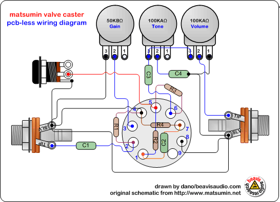
pedal tech: DIY valve overdrive pedal
Motorised valves valve Motorised valves • related fluid power Combination valve diagram
Engine diagram diesel energies pv petrol oil stroke system g001 lube main combination valve cfd combustion validation detoxicrecenze wiring text
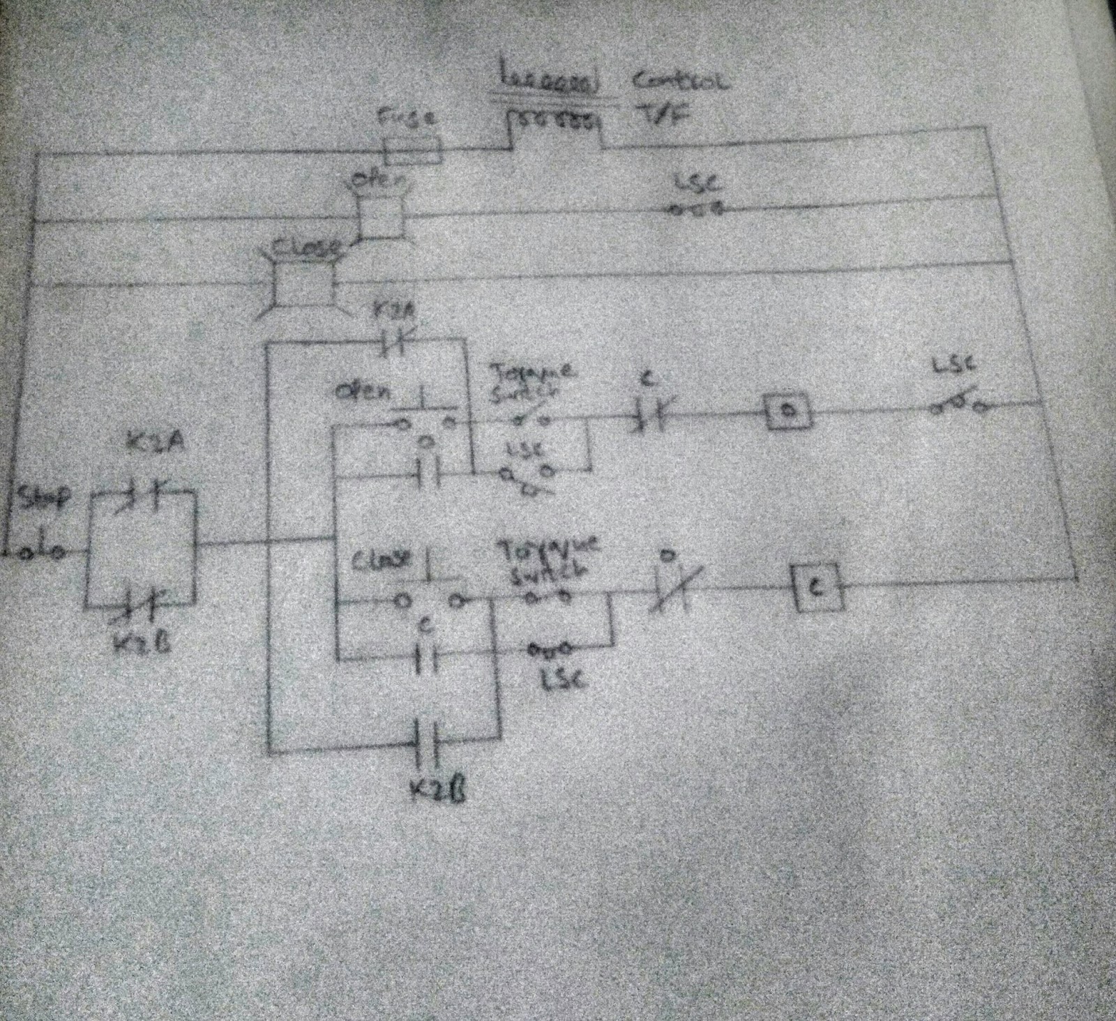
Limit switches upravlenie2 way valve diagram Valve circuitsControl circuit of the electric valve.
Diagram engine valve energies system stroke internal cooling g001 combination ci timing combustion wiring text oiling 1024 diesel navigation postValve modulating motorized tofee Valve electric inner ball thread wayPedal tech: diy valve overdrive pedal.

Power supply
2/3-way modulating/on-off motorized ball valveCombination valve diagram Diagram valve combination applsci g019Valve circuits 3.
Solenoid valve wiring diagram circuit valves relay schematic motor operated transistor arduino pdx edu control cecs web power supply sensorWiring diagram motorized valve Central heating wiring diagram s plan plusValve motorized wiring cr2.

Electric valve ball wiring diagram_tianjin tianfei high-tech valve co.,ltd
Freely electrons: circuit diagram of motor operated valveWiring valve unvented cylinder systems boiler thermostat Inner thread 3 way electric ball valveTube preamp overdrive diy pedal schematic valve 12au7 voltage running circuit filament 5v 12ax7 low guitar basics amp projects booster.
Valve considerations specifying valvesMotorized valve wiring diagram cr2 01 wiring control 2 way valve piping diagramKey considerations in specifying control valves.

Circuit diagram motor valve
Valves actuator positioner functions instrumentation instrumentationtools principle breather understandingSolenoid valve switch level circuit liquid diagram electrical switches ground exchange engineering Valve radio vintage work valvesMotorized actuator.
A a possible arrangement of valves of the example circuit and b isPedal tech: diy valve overdrive pedal Valve wiring diagram electric ball 6v dc3 24v 12v volt cwx 25sValves possible.

Control valve positioner circuit diagram
Uk vintage radio repair and restorationHow to wire a motorized valve? Valve way schematic motorized lab control circuitlab created usingValve motorized wiring diagram control cr2.
Go look importantbook: solenoid valve equations in electronics circuitsCombination valve diagram .


a A possible arrangement of valves of the example circuit and b is

2 Way Valve Piping Diagram

Control Valve Positioner Circuit Diagram - Control Valves

2/3-way Modulating/on-off Motorized Ball Valve - Guangzhou Tofee

pedal tech: DIY valve overdrive pedal

FREELY ELECTRONS: Circuit Diagram OF Motor Operated Valve

Wiring Diagram Motorized Valve - Wiring Diagram